Electricity can be one of the hardest concepts to grasp in this field if you don’t know what you’re looking at. Throughout this training, I have peppered in a lot of electrical concepts that build upon what we’re learning here, and practical applications of them. Don’t feel overwhelmed if you’re not catching on. If I’m being transparent, it took me much longer than I care to admit to understanding it enough to make diagnosing appliances an efficient manner.
Notes
- Load: Any device that does something when power is supplied to it – such as a lightbulb, a drain pump, a motor, a heating element.
- Switch: This is not a load. It is a device used to open and close a circuit.
Drawings: I drew the drawings in Google Docs. They’re not fantastic, but they get the point across. In the drawings, I do what I can to show you where line and neutral are based on the circuit as it sits. Pay close attention, because understanding where Line and Neutral are is a critical aspect to understanding how to interpret what your meter is telling you.
A Circuit
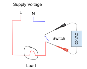
A circuit is a complete path in which electricity flows. If the circuit is CLOSED, it is complete. In other words, a closed circuit will cause a load to activate. If you have a line and neutral wired directly to a light bulb, the light bulb will turn on.
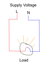
When both line and neutral are supplied to the load, you will see Neutral on one side, and Line on the other side. The load is using the full 120 VAC supplied to it to work.
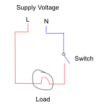
Now, if we were to put a switch in the circuit, and open it, the circuit would be OPEN. The light would not be on because it is not receiving both line and neutral.
Voltage Drop
When 120 VAC is supplied to a load, that voltage is “dropped” across the load. The load uses all the voltage if it’s the only load or resistance in the circuit. So, if you were to place your meter leads on either side of the load, you would expect to see 120 VAC on your meter.
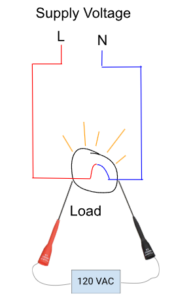
REMEMBER: As we learned in the previous module, voltage is the potential difference between two points. I am going to say this again and again, and then again throughout this training: Voltage is the potential difference between two points. Those two points are where you meter leads are placed.
Now, let’s take what we know about voltage drop and voltage potential, and look at various spots on an open circuit.
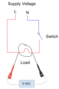
With the switch in the open position, we are getting 0 VAC when we have our meter leads across the same spots as before. The red line has 120 VAC going through it. It’s live. It will bite you if you’re not careful. But why are we not seeing 120 VAC? Why 0 VAC?
When you’re looking at a wire diagram, you will have to trace out how the load is getting its line and neutral. With the diagram above colored in, it’s much easier to understand why we are getting 0 VAC. There is no potential difference in voltage between the two points. You are reading the same side of the line. When a load does not have line and neutral to it, it becomes a simple conductor – no different than a length of copper wire.
Now, if we were to move the leads across the switch, let’s see what happens:
We see 120 VAC again. And I bet by now, you know why …. Bingo: there is a voltage potential difference between the two points that our leads are at.
Let’s expand on this just a smidge more. In the diagram below, we now see a Ground symbol (green). Ground has the same voltage as Neutral – 0 VAC. Ground is a physical establishment between an electrical circuit and the earth.
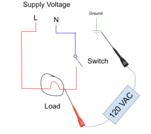
Again, we are seeing a voltage potential difference between the two points – Line (120) and Ground (0).
Application
Now, all of that might be interesting, but how is this useful when diagnosing appliances? I’m glad you asked! Let’s take what we learned and apply it to an GE gas oven igniter circuit.
The “Bake Glowbar” is our load. It needs 120 VAC to heat up. Drawing out the diagram, we can see how it gets its Line and Neutral.
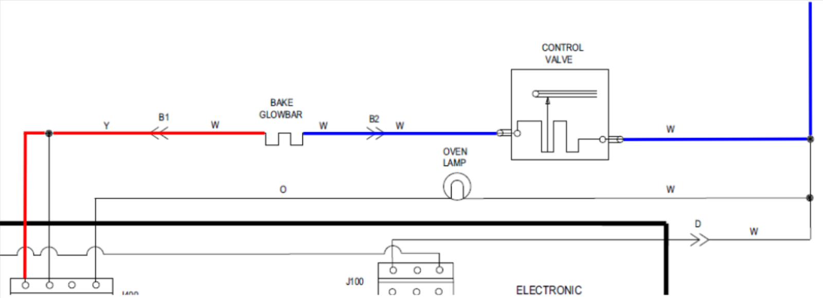
If we were to place out leads on either side of the glowbar in its current state, we would expect to see 120 VAC The control board is sending line voltage, and the control valve is connecting Neutral. The Glowbar is dropping the entirety of the voltage across it.
Now, let’s make things a bit more interesting. You’re out on a service call and don’t have the luxury of a diagram with the colors showing you where voltage is and where it is not.
You’re at the igniter and you back-probe the connection to check for voltage. You start a bake cycle and hear a click on the control board. You get 0 VAC, as shown above. Well, you think, we’re not getting any voltage. Bad control board. You toss a new board in, test the unit, and it’s doing the same thing.
Just because we are reading 0 VAC does not mean that we don’t have voltage. It means there is no voltage potential difference between the two points at which you are testing. Yes, the board might not be sending voltage. But you don’t know that based on a 0 VAC reading when both leads are in the circuit, without making an additional check.
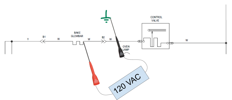
Now, let’s say we’re getting 0 VAC across the igniter, but when we place one lead on the igniter and the other lead on a Ground, we all of a sudden get 120 VAC. What does that signify? Take a moment before reading on and think about what this means.
To ground, we are getting 120 VAC, but across we are getting 0 VAC. A circuit needs WHAT to work? – A line AND a neutral.
When we check to ground, we have a voltage potential difference, but when we check across the glowbar, we don’t have a voltage potential. There is no voltage potential between 120 and 120 (more on this later, when we get to 240 VAC). This indicates that Line voltage is present. Which means … we are missing Neutral.
Can you see how this is a useful concept to understand when it comes to the diagnostic process? If at the igniter, we’re getting 120 VAC on each side of the igniter to ground, but 0 VAC across, then we’re missing our Neutral. We don’t need to focus on the control board. It’s doing what it should: It’s sending the 120 VAC. Knowing what we now know from that test, we know our issue is on the Neutral side of the circuit.
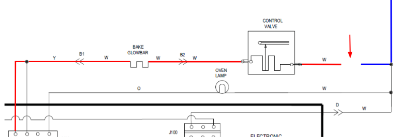
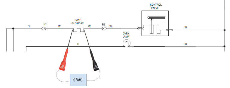
Now, let’s draw out the diagram based on what we’re seeing, and we’ll even go so far as to show our failure point. See the red arrow? That’s showing a broken wire on the neutral wire to the gas valve. Of course, when we’re diagnosing appliances, we don’t see this. But for training, seeing this, we now know what voltages we would expect to read, when considering voltage potential.
I won’t add the meter leads to this diagram, so use what you just learned to determine how you would zero in on what needs to be replaced if all you had was an uncolored diagram, and your meter.
- Across the glowbar: 0 VAC.
- Glowbar to Ground: 120 VAC.
- Across the gas valve: 0 VAC.
- Gas valve to ground: 120 VAC
And you’ll be checking each side of each of those loads to ground. If the Glowbar was open, you would get 120 VAC on one side, and 0 VAC on the other side. Same with the gas valve.
In the diagram above, you would read 120 VAC to ground on both wires to the glowbar, and at the Control Valve. If we saw that in the field, then we would know that we were missing neutral somewhere between the Control Valve and the wall, or at the wall.