Motor Diagnostics
In this module, we’re really going to dive deep into wire diagrams and learn how to conduct a majority of tests from easily accessible points. One of the things that always always gets to me is when I hear a tech tell me the unit won’t start, so they disassembled the dryer and checked the thermal fuse. It tested good, but they replaced it anyway, and the unit still won’t work.
Fact of the matter is, dryers that won’t start are among the easiest to diagnose, and we can do a majority of our initial testing directly from the control board or the timer. In this module, I am going to show you how.
The Schematic/Wire Diagram
There is a key difference between a wire diagram and a schematic. While knowing the difference between the two isn’t necessarily important, it’s good to know there is a difference. The thing to remember is that both of these technical sheets are like gold to anyone who wants easy diagnostics rather than a bunch of disassembly.
Wire Diagram
A wire diagram shows you the physical layout of the wiring. I have found wire diagrams the most useful in refrigerators where you’re looking for where wires might be routed and where connection points may be. I don’t often use these unless I absolutely have to because some of them look like the engineers threw a whole bunch of spaghetti at a wall and took a photo of it. You’ll spend inordinate amounts of time tracing out the wires, and they’re really not as practical unless you need a more in depth understanding of where the wires are going throughout their entire journey.
Schematics
Schematics, on the other hand, show the plan and function of the electrical circuits in a digestible manner. For a majority of our coursework, we’ll be looking at schematics and breaking them down. These will be our bread and butter.
Whirlpool Electric Dryer
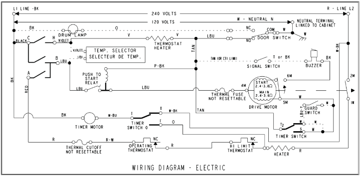
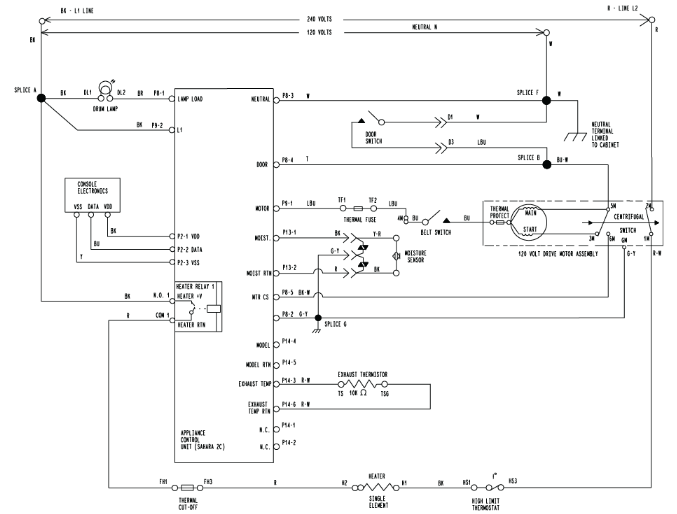
We’re going to start with two different Whirlpool electric dryer wire diagrams. I have found this brand to have relatively simple technical data, so it’s a great place to start.
Take a look at the two diagrams below. Do either of them daunt you? Do either of them make your head hurt thinking about how to decipher them? If you answered yes, then great! That means this module will help you!
The Key to Deciphering Wire Diagrams
The key to deciphering wire diagrams is to reduce the problem. I know we haven’t talked about what constitutes a circuit in great detail yet, but in essence, in order for a circuit to be “complete,” it must have an uninterrupted path to line and a neutral. Fortunately, we already know what Line is (120 VAC) and what Neutral is (0 VAC). A circuit is complete, or “closed,” if load has an unbroken Line and Neutral.
When you reduce a problem to the statement “How is a load getting its line and neutral?”, you can zero in on what is relevant and cast aside what is not. This, my friends, is the key to deciphering and reducing wire diagrams to its relevant data.
The Motor
The dryer motor is the same in both gas and electric. In order for this motor to run, guess what? It needs a Line and a Neutral. With those two present, the electrons will flow and our load will kick to life.
When we are called out to a dryer that won’t start, yes, we can rip the unit apart and test the thermal fuse. But what happens when you do that and the thermal fuse is good? Do you just start replacing parts?
How about this? What if I told you you can test entire circuits from the contacts on the timer, or directly from the control board? What if doing so shows you a circuit is complete? Would you spend the time disassembling the dryer to test parts? What if after disassembling and testing, you find that the control is not sending voltage and all that disassembly was unnecessary?
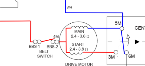
If our motor will not start, we do not need to look at the rest of the wire diagram. All we need to look at is the motor circuit. Line voltage is RED, Neutral is BLUE.
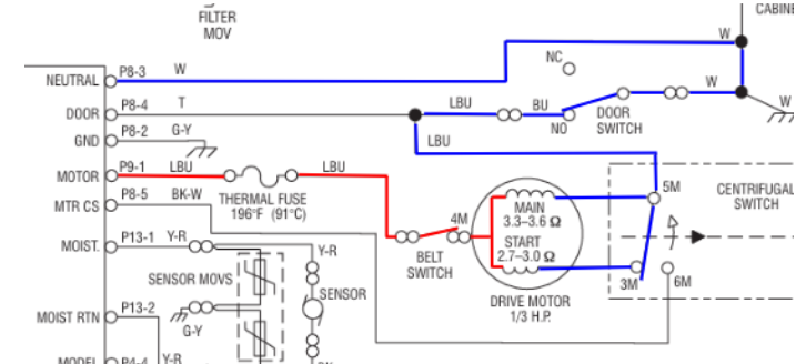
With the above diagram, we see the motor circuit.
- We can test from those points to see if the control is sending voltage when a cycle is started.
- We can disconnect the loads and ohm the circuit to see if it’s in spec, or if it’s OL (“Open Line”).
Motor Theory of Operation
The motor in your dryer is a critical component, responsible for turning the drum and, in some models, powering the blower that circulates air through the machine. Let’s break down how it operates and what makes it work so efficiently.
The Role of the Windings
A typical dryer motor has two sets of windings: the main winding (also known as the run winding) and the start winding. Both windings are connected to Neutral in the wiring diagram, which might seem confusing at first. Let’s clarify:
- Start Winding: This winding has lower electrical resistance and is designed to provide the initial torque required to get the motor spinning. When the motor is in the OFF state, the centrifugal switch connects neutral to both the main and the start winding.
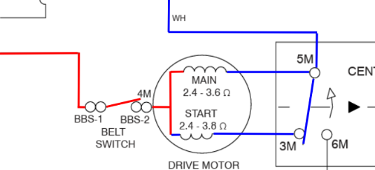
Electricity always follows the path of least resistance. When power is applied, current flows predominantly through the start winding because of its lower resistance. This generates the initial force needed to kickstart the motor.
Main Winding: This winding is responsible for keeping the motor running once it has started.
Once the motor reaches a certain speed, the centrifugal switch engages. This switch is mechanically driven by the spinning motor shaft. Here’s what happens:
- The switch disconnects the Start Winding from Neutral, effectively taking it out of the circuit.
- Current then flows solely through the main winding, which maintains the motor’s operation with less power draw.
This transition improves energy efficiency because the start winding, which is designed for short-term use, is no longer consuming electricity. The main winding pulls less current compared to the combined draw of both windings during startup.
Connecting L2 to the Heater
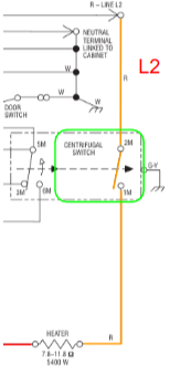
In dryers, the centrifugal switch also plays another important role: it connects Line 2 or Neutral to the heater circuit. This ensures the heater only operates when the motor is running, a safety feature that prevents the dryer from overheating if the drum is not tumbling.
In the diagram shown, this is an electric dryer. Line 2 comes in from the terminal block, stops at the centrifugal switch.
When the motor kicks to life, the centrifugal switch takes the start winding out of the circuit, and closes the L2 contacts to supply L2 to the heater.
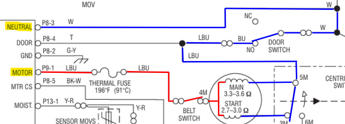
Testing From The Control
When diagnosing a motor that isn’t powering on, there’s no need to examine all the other loads. Instead, we can focus specifically on this circuit. While the schematic doesn’t explicitly confirm that the control board is sending line voltage, we can use deductive reasoning to pinpoint the issue. Since the Neutral connection routes through the door switch, the only remaining path for the line voltage is through the P9-1 connector on the control board.
Voltage Testing – To The Board
There are non-invasive tests we can conduct first that will indicate whether we have voltage to the unit:
- Does the user interface (if present) turn on and respond, or light up?
- Does the drum light (if present) turn on and off when actuating the door switch?
If the dryer is not starting, I always start with a voltage test at the outlet. After all, without the correct voltages, none of the loads will function! I’ve learned this the hard way—jumping straight into resistance and continuity tests to find everything checked out, only to later discover that the real issue was missing voltage somewhere, or a tripped breaker.
Let’s start with a control board dryer first. Since we know our board connects line voltage to the motor, it would be logical to first ensure our control board is actually getting that proper voltage to send out, right?
Using the schematic, let’s figure out how our control board is getting that voltage to send to the motor.
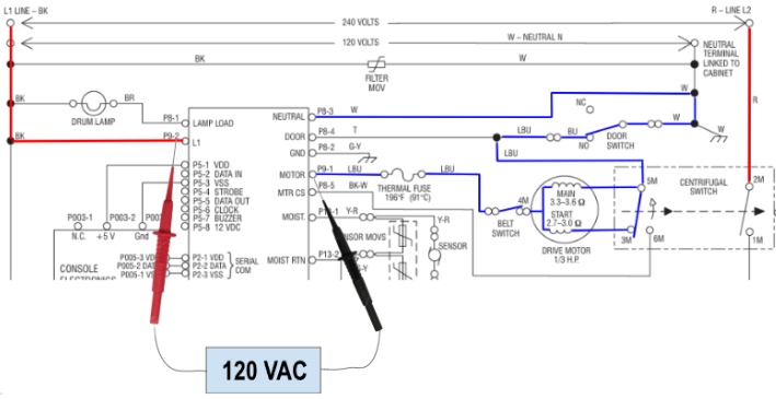
At those two connections (P9-2 and P8-3), we should have 120 VAC all the time. Whether the unit is on or off. Those line and neutral connections are what sit there, and wait to be directed elsewhere.
The Motor Circuit
Motor Off (No Cycle Started)
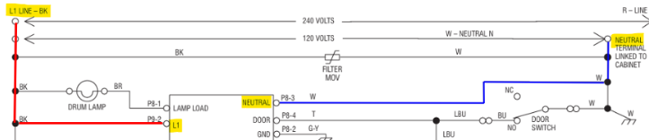
When the dryer is off and the motor is not running, let’s look at where voltages would be.
Remember, when a load does not have BOTH Line AND Neutral present, that load becomes a simple conductor. Nothing more than a piece of wire. With the door switch shut, Neutral back-feeds all the way to where the control board would send line voltage. But, with the relay on the board in the open position, there is no line voltage present.
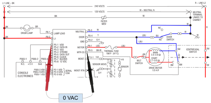
With it drawn out, it’s a bit easier to see what we’re talking about. Notice how the blue color is the Neutral, and it back-feeds all the way up to the board when the unit is in standby mode?
If we were to check VAC from where L1 enters the board to where the board sends line voltage to the motor, we would read 0 VAC. There is a voltage potential difference between Line coming into the board, and Neutral (0 VAC) back-feeding through the motor to the control board.
If you were to start a cycle, you hear the board click, and you still see 120 VAC at those two test points, guess what? The relay has failed. It’s not sending voltage to the motor.
Motor On (Cycle Started)
In a working circuit, if we were to leave our leads at the same spot and start a cycle, our voltage would look something like:
We’ve gone over this before, and I’m really trying to drive this home: voltage is the potential difference between two points. When the relay on the board closes, we are supplying line voltage from the L1 connector on the board (P9-2, in the diagram) to the P9-1 connector (the motor circuit). That is the same leg of voltage. There is NO potential difference between those two test points. All a relay is are two contacts that close to complete a circuit.
So, when we’re reading 0 VAC at those two test points whereas before we were reading 120 VAC when the relay was opened, all that signifies is that the relay closed and is passing that voltage through.
If you were to see 0 VAC on the test points above, this generally signifies that the control board is sending voltage to the motor circuit. If your motor is still not kicking on, then you’ve probably got an OL on the motor circuit.
Summary
In this module, we went over how to check the motor circuit from the control board. In the next module, we’re going to dig into timer models and making checks from the timer.