Understanding Wire Diagrams and Schematics
If you’re new to reading wire diagrams and schematics, or if they daunt you, then this course if perfect for you. While this module is going to go over the bare minimum, throughout the entire course we really drive home how to apply what you’re learning in a digestible and visual manner.
In this module, we’re going to lay the foundation with some very simple concepts that you can store in the back of your mind for the future modules when we’re reviewing the diagrams.
What is a Wire Diagram?
A wire diagram, simply put, is a roadmap for how a circuit works. It’s a visual representation of an electrical circuit. It shows how components are connected using symbols and lines instead of physical pictures.
If you were to wire a drain pump directly to the wall, you might see something like this as a wire diagram:
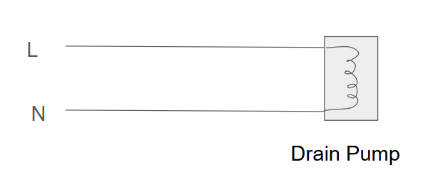
With wire diagrams, what we care about is how the loads are receiving their voltage.
In the above example, if the drain pump were not working, we have 2 test points. We know it needs 120 VAC. So, we might start by checking for voltage at the outlet.
- If 120 VAC is present there, at the source, then we would next check at the drain pump.
- If 120 VAC is present at the drain pump, but the drain pump is still not working, then we’ve got a bad drain pump.
- If 120 VAC is present at the outlet, but 0 VAC is present at the drain pump, then we’ve got a broken wire somewhere.
Now, let’s add to it.
You’re on a service call. The drain pump is not working. Without looking at the diagram, you check voltage at the outlet. 120 VAC. You check at the pump. 0 VAC. Wiring, right?
Well, let’s look at the wire diagram.
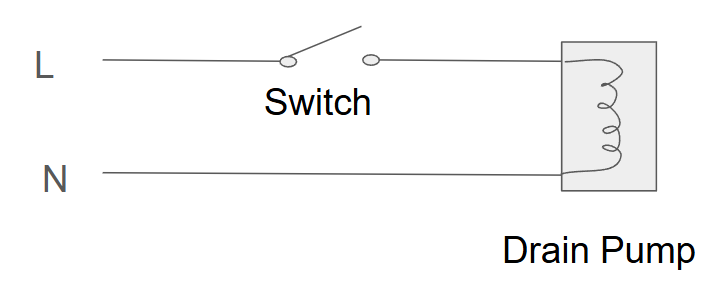
Look at that! Before looking at the diagram, all we knew was there was 120 VAC at the wall and 0 VAC at the drain pump. But now we see there is a switch wired in on the line voltage side. We would want to check that switch before landing on a faulty wire harness.
Using and understanding wire diagrams is critical. Not only can you see what stands in the way of the load from getting its line and neutral, you can also find easy test points.
Throughout this training course, we’re going to go over testing from convenient locations and feeling confident about it.
The Basics
We know that an electrical load, such as a drain pump, needs BOTH line and neutral present at it, AND a closed circuit to operate.
Let that sink in. Understanding that basic concept alone is the fundamental concept to understanding and deciphering wire diagrams.
That said, when you are looking at a particular load (again, let’s say the drain pump), all you need to do is trace out how that load is getting it’s line and neutral.
Along the journey of tracing out how that load is getting its line and neutral, we might see some switches along the way. You might see it connected to a control board.
Questions
When you’re focusing on a load that is not working, you need to ask yourself the following questions:
- How is the load getting line and neutral?
- What stands between the outlet and the load?
Let’s further simplify the overall thought process. It’s easy to overthink things when you get control boards and switches.
- A drain pump requires 120 VAC to work. You can plug the drain pump directly into the wall, and it will power on and will run.
- To automate operations, add in a control board with a relay for the drain pump. That relay is a switch. Now, between the wall and the drain pump, you have a relay. If that relay fails, the drain pump circuit will be “open.”
To understand wire diagrams, you need to determine what stands between the wall and the load. And then it’s a matter of seeing where the voltage stops.
(We’ll get into wire diagrams vs. schematics later on.)