In this module, we’re going to look at the three types of circuits you’re going to find in appliances, and in electricity in general. These are Series, Parallel, and Series Parallel. It’s imperative that you know what they are, their differences, and what happens when a failure occurs in a given circuit.
Series Circuit
A series circuit is a simple circuit where all the elements are in a single path. If anything in that path were to fail open, then the circuit would become open and none of the loads on that circuit would work. Below is an example of a Series Circuit.
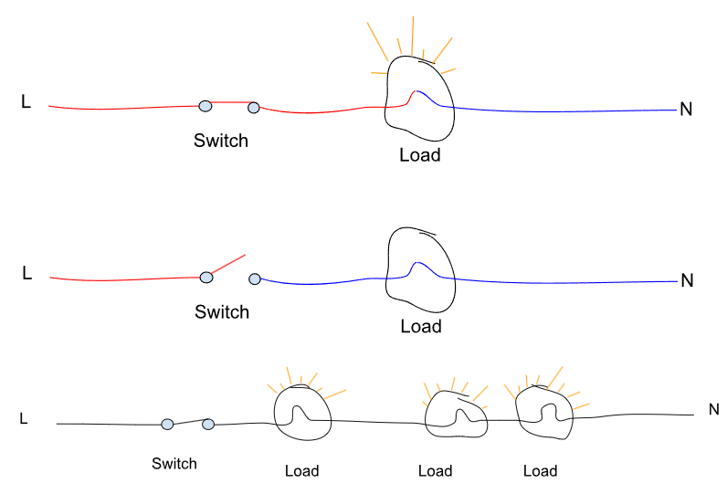
As you can see, a series circuit can include one load and one switch, or it can even include multiple loads and multiple switches. If any of the switches or loads in the series circuit fails or is open, then that opens the entire circuit and none of the loads will work.
The thing to remember is that at minimum, in a series circuit, there needs to be at least one resistive load. Otherwise, you’d have a dead short.
Short
Resistance is what restricts current flow. All loads will have resistance. For instance, a drain pump in a series circuit could be 20Ω. That is the resistance placed in that circuit, and it is this resistance that prevents current from rising to infinity, and beyond – tripping breakers, melting wires, causing a fireworks show.
A short is a situation in which no resistance stands between line and neutral.
If line and neutral were to meet one another without a resistive load between the two, let’s do some quick math to see what is really happening.
We’ll get into Ohm’s Law here soon, but for now, the current (amps) in a circuit can be calculated by dividing Voltage by Resistance. So, if we have a 120 VAC circuit and a 20Ω drain pump, we would use this equation: 120 ÷ 20 = 6. So that drain pump circuit would be pulling 6 amps. If the washer is on a dedicated circuit with a 20 amp breaker, the breaker will not trip.
Now, let’s assume we take the 20Ω drain pump out of the circuit and connect Line to Neutral. For starters, we would need to figure out the resistance on the circuit. The resistance on a length of wire should be very minimal. We don’t want to lose power on a resistive wire. If you ohm of a length of wire, you’re generally going to see very low resistance. Maybe 0.1Ω.
So, let’s calculate the current draw of 120 VAC on a 0.1 ohm circuit.
120 VAC ÷ 0.1 ohms = 1,200 amps.
What about a wire with .01 ohms of resistance?
120 VAC ÷ .01 ohms = 12,000 amps.
And what about .001 ohms? You get the point.
As you could imagine, 1 circuit trying to pull 1,200, 12,000 or 1,200,000 amps on a 20 amp breaker will certainly trip the breaker. But you’re likely going to get enough electrons in that short period of time to cause a scene.
Parallel Circuit
A parallel circuit is a circuit in which there are multiple paths for electrical current to flow. The key differentiating factor with this circuit is that if one load fails, the others will continue to work. When looking at the diagrams below, a load needs an uninterrupted path to line and neutral to work.
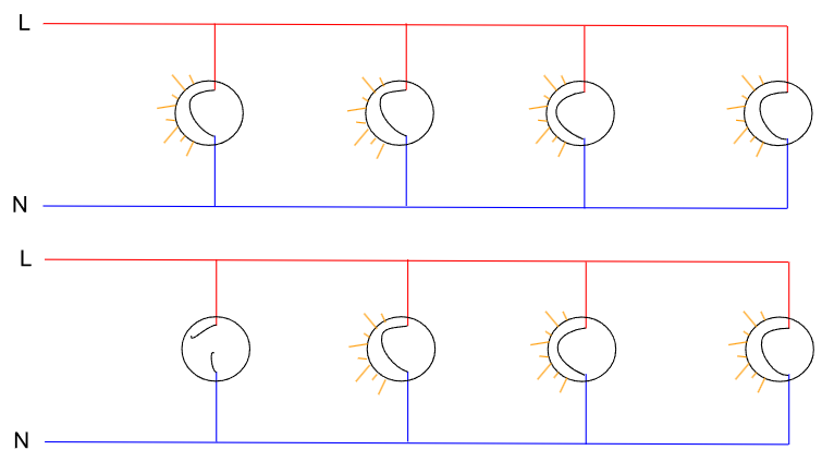
In the top diagram, all the loads are working. Each one has its own individual line and neutral.
In the second diagram, you can see that the first load in the circuit diagram is open, so it’s not working, but all the other loads are working. With the drawn out diagram, it’s easy to see why. Even though the first load has failed, that load does not break the circuit for the other loads. The other loads still have an uninterrupted path to line and neutral.
Series Parallel Circuit
This circuit combines the two. Below are 3 diagrams showing what you’ll see at various failure points. When you’re viewing the diagrams, remember what we went over with where voltage is in a circuit when a load is open. And remember that a load needs Line and Neutral to work. Closely inspect each diagram, and you’ll start to understand how a load gets its Line and Neutral – this is a critical step to take when diagnosing appliances.
If a load is not working, we want to ensure it’s getting Line and Neutral. This is where the wire diagram or schematic comes in handy. We’re really going to dive deep into understanding wire diagrams in this entire course. In this module, we’re setting the groundwork for understanding them.
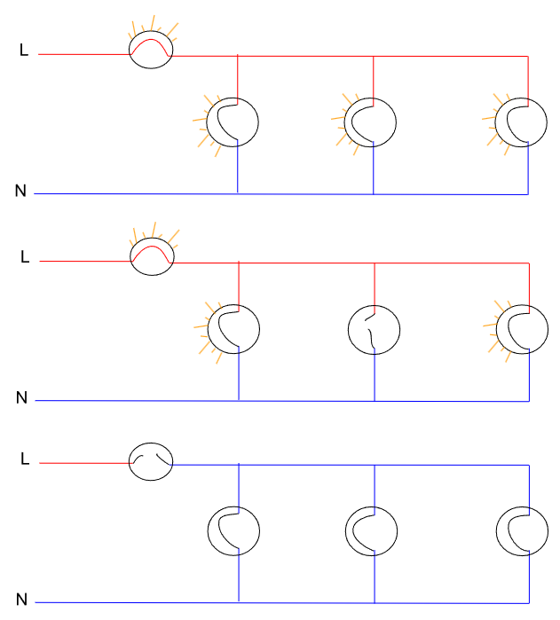
- In the top diagram, all the loads are working.
- In the middle diagram, one of the loads in a parallel circuit has failed, but all the other ones are still getting line and neutral.
- In the bottom diagram, the first load has failed, and it removing line voltage from all the other loads downstream. None of the loads work.
Summary
This was a brief, yet important section. When you are out on a service call and are reviewing a wire diagram to see how a load gets its voltage, you’re going to be looking for what stands between that load and the supply voltage. For electric dryers, you’ve got thermostats, control boards or timers, centrifugal switches, etc.
It’s essential to know how circuits work to properly diagnose. With time, you will get faster.