Electric Dryers – Troubleshooting
We’ve learned what we need to know about electricity and the components that you’re going to find in an electric dryer. Now it’s time to apply those to the diagnostic process. Throughout most of this training, I’m going to impress upon you techniques you can use to diagnose an appliance with minimal disassembly. In order to learn how to do this, you have to learn how to read and understand wire diagrams.
While some of the content in this module may seem the same as the previous module, we’re expanding on that, so pay close attention.
We might be brush across the same things we went over before, and there’s a reason for that – it’s to remind you of their operations and their functionality in a repeated manner to ingrain them into memory.
Diagnosing
It will take time to familiarize yourself with the various loads, switches, and fuses, and their purposes. It took me forever to finally catch on to what the various fuses in a dryer do, and the symptoms associated with their failure. Once you learn what loads and switches do and the symptoms of their failure states, you’ll be knocking out dryer calls like they’re nothing.
Consider this: Customer says their dryer is not heating. It will turn on, it will tumble, but it will not heat.
Consider this: Customer says their dryer will not start at all.
There are two distinct differences between the two, and there are a few specific failures that will be attributed to one over the other. In order to know which is which, and where to focus your efforts, we would look toward the schematic to see how the loads are receiving their voltage.
No Start
When you’ve got a unit that will not start a cycle, we would want to look at a few things.
- Is the unit getting proper voltage?
- Is the motor circuit closed?
- Is the control system sending voltage to the motor?
When it comes to checking voltage to the unit, I will be the first to admit that I’ve disassembled entire units and checked every component before checking the outlet, just to find the breaker has been tripped. When you’re out on a service call for a dryer that is not starting at all, always start with your outlet voltage! (Refer back to the section on checking outlets and 240 VAC for the process on that.)
If you’ve got 240 VAC at the outlet, then what? You’d want to check the schematic to see how the motor is getting its line and neutral. After all, when you start a cycle, it’s the motor that kicks to life. If it’s not doing that, we need to see where the failure is.
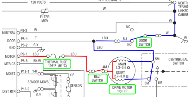
When we trace out how the motor gets its Line and Neutral, we can see what switches or fuses stand in the way.
- Thermal Fuse: This fuse is on the blower housing. If the temperature in the blower housing gets too hot (generally due to an airflow obstruction in the vents), then the fuse will pop open and we will no longer have line voltage supplied to the motor.
- Belt Switch: Not all dryers have these, but if they do, this is a switch that generally sits beneath the idler pulley. When the belt is tensioning the idler pulley, the switch is in the closed state and is sending line voltage to the motor. If the belt breaks, a spring on the idler pulley pulls it down and it makes contact with the switch.
- Drive Motor: As mentioned previously, there is a thermal protection bi-metal built into the motor. If the motor overheats, the bi-metal will open and the motor will be deprived of line voltage.
- Door Switch: The door switch connects neutral to the motor circuit. If the door switch has failed, then the motor will not have a clear path back to neutral. Don’t get tripped up thinking the Tan wire on P8-4 is the neutral for the motor circuit. On this unit, it’s there as a sensing line so the control board can see if the door is opened or closed.
No Heat
When you’re out on a service call for a unit that runs, but is not heating, we would focus our efforts on the heating circuit. As with the motor circuit, we want to see what stands in the way of the heating element from getting both legs of line voltage.
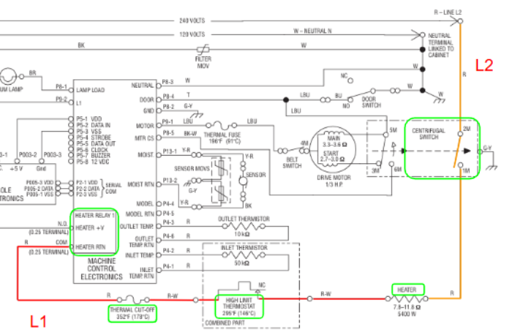
In the above example where a control board is used:
- Heater Relay: Stops L1 from reaching the heating circuit until the control is ready to start the heating cycle. This is a simple relay that the control board itself opens and closes.
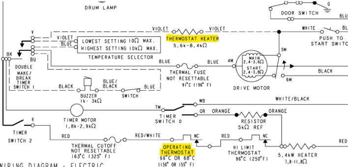
- Thermal Cut-Off: The thermal cutoff is one of the two thermostats that sits on the side of the heater housing. It is wired in series with the high-limit thermostat. One is a redundancy in case the other fails. This one is a non-resettable fuse. If it blows, you will need to replace it, and determine why it blew in the first place.
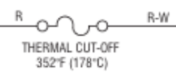
-
- With this schematic symbol, it’s nice enough to designate it as “Not Resettable.” It even shows you the breaking temperature.
- High Limit thermostat: This is the second thermostat on the side of the heater housing. Per the schematic symbol, this is a self-resettable bi-metal thermostat. If the temps get too high, the bi-metal strips will bend away from one another, then will close when cooled down. If it happens to fail (such as getting fused shut), then the thermal cut off is there to break the circuit.
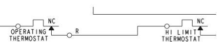
-
- Notice the schematic symbols for these two? The “NC” designation and the arrow indicate that this is a resettable thermostat. “NC” stands for Normally Closed. So, in it’s normal state, the contacts are closed. When heated, the contacts open.
- Heater: We went over a few failure states in a previous module, such as grounding. But more often than not, you’re going to find that the heater is open (OL).
Centrifugal Switch: When the motor kicks to life, the centrifugal switch engages, and closes the L2 circuit to the heater.
Temperature Regulation
Cycling Thermostat
On timer dryers, the chief component that regulates temperatures is the Operating Thermostat, also referred to as the Cycling Thermostat. This thermostat is a self-resetting bi-metal switch, and it’s located on the blower housing. When temperatures in the blower housing reach a certain range (155 degrees), it opens, and cuts voltage to the heater. Once those temperatures reduce, the bi-metal contacts close, and L1 is supplied back to the heater.
So, when we have an airflow restriction, the temperatures at the cycling thermostat will remain higher for longer. You will have the same moisture dense hot air just hanging out, rather than being expelled from the unit.
On some cycling thermostats, you’re going to see 4 electrical spade connectors. The large ones on the sides are what line voltage supply to the heating circuit. They are routed across the bi-metal strips.
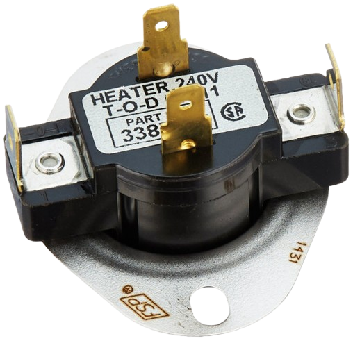
The two smaller, gold spade connectors are for the bi-metal heater. When a customer wants to have a lower heat setting, the temperature selector knob will send voltage to the heater inside the bi-metal, and it will trick the bi-metal into opening sooner. Pretty neat, huh?
When you’re looking at the schematic for this type of dryer, you’re going to see the Operating Thermostat in series with the heater and the other fuses and thermostats. While the thermostat heater is part of the cycling thermostat itself, it’s not shown that way in the diagram.
Thermistor
With the incorporation of control boards into appliances, manufacturers have started using thermistors. These are temperature sensing devices that change the resistance value based on temperatures. On dryers, they are generally Negative Temperature Coefficient (“NTC”) thermistors – when temperatures rise, resistance decreases. When temperatures decrease, resistance increases. In other words, an inverse reaction. We’ll get more into PTC and NTC thermistors in a later module.
For now, what you need to know is that a thermistor changes its resistance based on temperature. The control board uses that information to determine when to cut on and cut off the heat.
Thermistors are DC loads. The control board send a small DC voltage through the thermistor, and it then calculates the voltage being dropped across it. Inside the board, there is a voltage divider circuit. (Not going to get into the particulars of that here.)
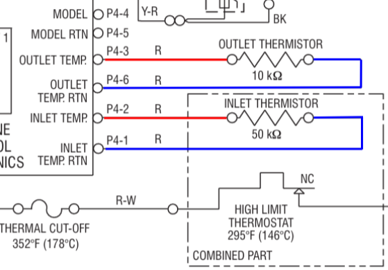
Take a look at the diagram above. We can see 2 thermistors – an outlet, and an inlet. Both have different resistance values, and those resistance values are what to expect at room temperature.
Also notice that there is a dashed line around the High Limit Thermostat and the Inlet thermistor. This indicates that the inlet thermistor on this unit is part of the high limit. In fact, these are much like the bi-metal heater on the cycling thermostat.
Testing
If you suspect a thermistor is out of range, it’s as simple as accessing the control board, disconnecting the connector with the thermistors, and getting a resistance (Ω) value on the two wires. At room temperature, the values should be as shown on the diagram or in the tech manual.
Remember, thermistors are pretty precise. If you were to read 11kΩ on the outlet thermistor and it’s at room temperature, then the thermistor is likely okay. It’s if you were reading, say, 2kΩ at room temperature where you might have an issue.
Summary
There really is not that much to dryers once you get acclimated to them. The key is that you verify the complaint before you dive into diagnostics, and that you reduce the problem to what is relevant. There are times where you will find that there is not even an issue with the dryer, but rather it’s with the ventilation.
In the next module, we’ll dive into a few ventilation testing methods.