Overview
In this module, we’re really going to dive into voltage, sine waves, and what you need to know to properly understand what your meter is telling you. I can’t tell you how many times I see techs misinterpret what their meter is telling them and end up wasting time and replacing the wrong parts. We’re going to dive deep into this in this module, then brush across it in subsequent modules. Pay close attention!
The Heating Element
The heating element is what heats the dryer. We all know that. But how do they work? Yes, it’s as simple as getting 240 VAC to it, but there is actually a bit to understand.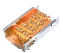
When you’re looking at a heating element right out of the box, you’ll see a metal casing and the coils inside. On the outside of the metal casing, you’ll see two terminal connectors (sometimes more, depending on the model). When we plug in the two wires to the terminals and supply two legs of 120 VAC that are out of phase with one another to it, the coils start glowing red and producing heat.
To start, even though the casing to the heating element is metal and the coils inside are nichrome, the two of them are designed to not touch one another. If the coils were to touch the metal casing, this would cause the heating element to become “Grounded,” and this is not a good thing. When not grounded and energized with a 120 VAC line but no voltage potential (0VAC), nothing will happen. There is no voltage potential.
When part of the nichrome touches the metal housing (the housing being 0 VAC), now there is a voltage potential and current starts to flow. The element would start to heat up, although at half the BTU output of if the full 240 VAC were present.
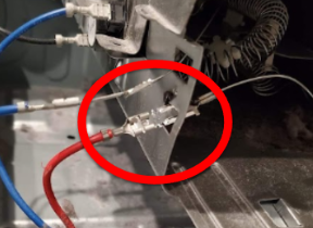
You would not see a “short” if the nichrome wire were touching the housing since the nichrome is a resistive load. You WOULD see a short if a leg of voltage BEFORE the nichrome wire were to touch ground, as is the case in the image.
Most configurations nowadays have a line break on each leg of voltage to the heater so if the heater nichrome wire were to ground out, nothing would happen. The centrifugal switch opens L2, and either the timer or the control cuts L1. If the timer contacts for L1 to the heater were to fuse shut, and the nichrome were to be grounded, the element would heat up.
Electrical Refresher
- Understanding Voltage and Current:
- Voltage (V): This is the electrical pressure that pushes current through a circuit.
- Current (Amps): This is the flow of electricity through the circuit.
- 240 Volts AC (Alternating Current): In the U.S., 240 VAC is supplied as two “hot” wires, each carrying 120 volts out of phase with each other. This means that while one wire’s voltage is at its peak positive, the other is at its peak negative. This difference adds up to a total potential of 240 volts. (More on that here shortly.)
- Split-Phase Power:
- Most homes in the U.S. receive a split-phase 240-volt service.
- The two “hot” wires (L1 and L2) come from opposite ends of the transformer secondary coil, providing the 240 volts between them. At the breaker box, they are segmented.
- A third wire, the neutral, is connected to the center tap of the transformer coil. This allows appliances to access either 120 volts (L1 or L2 to neutral) or 240 volts (L1 to L2).
How a Heating Element Works with 240 VAC
- Heating Elements and Resistance:
- A heating element (found in ovens, dryers, and water heaters) is typically made of a high-resistance material like nichrome wire.
- Resistance is the key to generating heat: when electricity flows through a material with high resistance, it encounters opposition to the flow, converting electrical energy into heat energy.
- Connection to 240 VAC:
- The heating element is connected across the two hot wires (L1 and L2). With no need for a neutral wire in this case, it gets the full 240 volts.
- The element’s resistance limits the current flowing through it, based on Ohm’s Law. Current (I) = Voltage (V) / Resistance (R).
- Heat Generation:
- You can calculate the heat generation using Watt’s Law and some other equations, but I have never really had an instance where I’ve needed this metric. It is important, though, to understand, as with Ohm’s Law, there is a correlation between the metrics.
Safety Considerations:
- Proper Grounding: Ensures stray currents are safely directed away, protecting both the user and the appliance. There are generally support clips that lift the nichrome heating element away from the metal heating housing to prevent this. Over time, the nichrome can heat up and can bend away and will sometimes make contact with the housing. This is when grounding occurs.
- Circuit Breaker: A 240V circuit requires a double-pole breaker that disconnects both hot wires simultaneously in case of a fault, such as a short. This breaker must be rated for its intended use. Generally, this is a 30 amp breaker.
This principle applies to any appliance with a heating element, such as ovens, dryers, or water heaters. When diagnosing issues, always check for proper voltage supply, ensure the element’s resistance is within specifications, and inspect for any signs of damage or burnout.
Sine Wave
When we talk about alternating current (AC), we’re referring to the flow of electricity represented by a sine wave that continuously cycles up and down. This wave alternates between +120 volts and -120 volts, completing this cycle 60 times per second, which is measured in hertz (Hz). While we won’t dive into the specifics of hertz right now, it essentially indicates how quickly the sine wave alternates. In the United States, the standard frequency is 60 Hz. This alternating current is generated by massive generators that produce the sine wave by spinning magnets, creating the positive and negative voltage fluctuations.
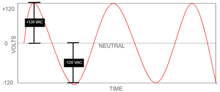
Now, this alternation happens so fast that our meters average it out and present us with 120 VAC. We won’t see our meters bouncing back and forth from +120 to -120. But remember, that 120 VAC is when testing to Neutral, a known 0 VAC source.
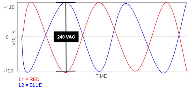
So, how do we get 240 VAC? Simple. We take two separate 120 VAC lines that are out of phase with one another, and we get 240 VAC.
Our reference point in a 120 VAC circuit is a Neutral, which is 0 VAC. That creates a potential difference of 120 VAC.
In a 240 VAC circuit, our reference point is the opposing 120 VAC. So, +120 VAC, and -120 VAC, which = 240 VAC. That creates a potential difference of 240 VAC.
Phases
But that begs the question, “What are phases?” A phase is the sine wave. When you’ve got a single phase of electricity, you’re looking at one single 120 VAC sine wave flip flopping from +120 VAC to -120 VAC. The key to getting that 120 VAC into 240 VAC is by incorporating another 120 VAC sine wave flip flopping out of sync with the other one. So, instead of measuring from + & -120 VAC to 0 VAC, we are measuring from +120 VAC to -120 VAC.
Understanding this concept is absolutely critical! Not only for understanding 240 VAC, but for understanding diagnostic processes when it comes to voltage.
Consider this (and trust me, we’re going to drive this point home): if you’re at a heating element that’s not heating, and you see 0 VAC across the heater element connections, but 120 VAC on each side to ground, what does that signify to you?
By now, it should signify that you are missing a leg of voltage. (If you’re not 100% on board with that yet, just wait. We dive into it in later modules when you’re looking at testing specific loads and voltages.)
Electron Flow
When working with 120 VAC and 240 VAC circuits, the behavior of electrons and the flow of electricity follow basic principles, but the way they’re delivered in the circuit changes depending on the voltage.
Electrons in a Circuit (Basic Concept)
- Electron Flow: In a circuit, electrons move from the negative terminal of a power source, through the circuit (doing work), and back to the positive terminal. This is known as current flow, and it’s measured in amperes (amps).
- Voltage: Voltage is the “push” or “pressure” behind the movement of electrons, measured in volts (V). The higher the voltage, the stronger the push.
- Alternating Current (AC): In an AC circuit like 120 VAC or 240 VAC, electrons don’t flow in one direction continuously. Instead, they oscillate back and forth, switching direction 60 times per second (60 Hz) in the U.S. This oscillation is what distinguishes AC from DC (direct current).
120 VAC Circuits
- How it Works: A 120 VAC circuit typically has one “hot” wire (connected to one side of the transformer) and one “neutral” wire. The hot wire provides the voltage (120V) and alternates its polarity, while the neutral wire is at 0V (ground potential).
- The electrons oscillate between the hot and neutral wires, doing work along the way (powering an appliance, light, etc.).
- Path of Electrons: The hot wire “pushes” electrons into the load (e.g., motor, light bulb), and they flow back through the neutral wire, completing the circuit. The neutral wire is connected to the ground at the electrical panel to maintain safety.
240 VAC Circuits
- How it Works: A 240 VAC circuit has two “hot” wires, each carrying 120V but out of phase with each other. This means when one wire is at +120V, the other is at -120V.
- The voltage difference between the two hot wires is 240V (because -120V + 120V = 240V).
- Path of Electrons: Electrons oscillate back and forth between the two hot wires. Since there’s no neutral wire in many 240V-only devices (like an electric range or dryer), the return path for the electrons is simply the opposite hot wire.
Why It’s More Efficient: Because the voltage is doubled compared to 120V, the current (amps) needed for the same amount of power is halved. Lower current means less heat loss in the wires and smaller conductors can be used.
Also remember this: Electrons are negatively charged. They seek positivity. When the electrons are on the -120 segment of the sine wave, guess what? They want to be at the +120 edge of it.
Summary
We went over quite a bit of critical infrastructure in your understanding of voltage in this module. It’s okay if you don’t fully understand it as of yet. It took me a while before I fully understood it. In later modules, we’re going to touch base on what we learned here, and apply it in practical scenarios.
Critical Tidbits
- Voltage is the potential difference between two points.
- Voltage is what provides current (amps) the pathway to the load.
- 240 VAC is the potential difference between two 120 VAC lines that are out of phase with one another.
- 120 VAC is the potential difference between 120 VAC and Neutral, which is 0 VAC.