Loose Wires
Electricity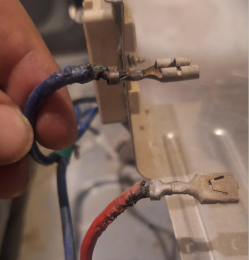
At some point, we have all seen burnt up wires when we’re out servicing appliances. But why did they burn up in the first place?
Simple: Something was loose.
Let’s break this down. A load needs a voltage potential difference on either side of the resistance for current to flow. A heating element, for instance, is a “resistive load.” If we have two separate 120 VAC legs of voltage (which would be 240 VAC), one leg on each side, then the 240 VAC is dropped across the resistance of that load.
When it comes to circuits, resistance obstructs current flow. It makes the current work harder. And when current is flowing, heat is generated. Thus, when you have a heating element that has 11Ω of resistance, we can use Ohm’s Law to calculate how much current is flowing. I will save the math here, but it’s about 21 Amps. The ultimate goal is to ensure as much of that voltage and current is supplied to the load so it can work at it’s full potential!
Now, what happens when we have a loose connection? The electrons then have to jump the gap on the loose connection to reach where they’re trying to go. And that resistance generates heat.
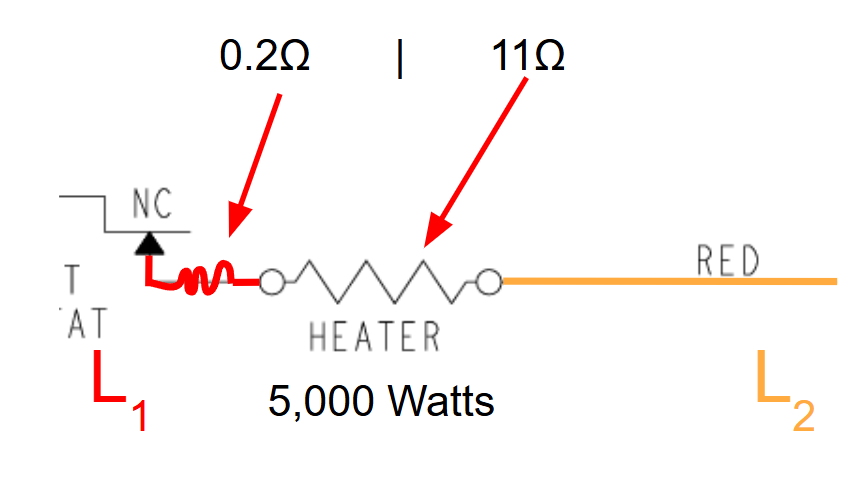
When we have a loose connection, be it a loose spade terminal or a wire not secure in the terminal, that loose connection generates resistance. In the above example, the loose resistance then generates a series circuit with the heater. And guess what? When you’re dealing with a series circuit, the voltage is dropped across each piece of resistance in proportion to the resistance of that particular section.
So all of a sudden, we’re going from the heating element getting all of the current to the heating element sharing some of that current with the loose connection.
While I am not going on inundate you witht the math here, if you apply Ohm’s and Watt’s Law calculations, we can determine that in the above scenario, the loose connection on the L1 side of the heater is generating just over 86 Watts of heat at that connection!
Understanding how electricity works is crucial to you knowing how a failure occurred, and how to prevent a failure from happening after you service an appliance! Make sure those connections are TIGHT!
Multimeter Thoughts
General, Electricity
When it comes to choosing a multimeter, this falls more into the realm of preferential than anything else, but there are a few meter settings that you as an appliance repair technician should not be without!
- Resistance Ω This is the setting we would use to check the intergity of a circuit or of a load.
- Volts AC Every major household appliance uses AC voltage, be it 120 VAC, or 240 VAC. And there are some applications where you’re going to see 12 VAC and 24 VAC.
- Volts DC On appliances where you’ve got computer control boards, you’re going to see more and more of DC circuits.
- Capacitance Otherwise known as microfarads, this is the setting used to check capacitors. You will find capacitors on washers, microwaves, refrigerators, and in other settings, depending on the configuration.
- LoZ This is a low impedance feature that can help you rule out ghost voltage.
- Amp Clamp While a load can show proper resistance, that does not tell you if there is a mechanical failure or not, or if the load is working up to par. Current is way you can tell if your load is working as it should.
- Thermocouple This is the temperature probe. Is invaluable on oven heat complaint calls, dryer airflow issue calls, and fridge temerature checks.
Multimeters can range anywhere from $20 all the way up to $1,000+, depending on the features, functions, and precision you’re looking for. And yes—there are real differences in build quality and accuracy between lower-end and higher-end meters.
But here’s the reality:
In appliance repair, you’re checking voltage and resistance the vast majority of the time. And when your goal is to determine whether 120 VAC is present or not, you don’t need a $400 meter when a $50 one will give you the answer just fine.
Since I got into appliance repair, I’ve consistently used a $45 meter from Amazon. It handles everything I need—residential, commercial, even HVAC work.
Now, when you compare it to a high-end $400 meter, sure, there are slight differences in readings. You might see something like 119.6 VAC on one meter vs. 119.2 VAC on another.
But here’s the key takeaway:
That difference is generally negligible for what we’re doing.
When it comes to diagnosing electrical issues, I can’t recall a single time where that small variation led to a misdiagnosis. The meter has always been accurate enough to confidently identify the problem. I am repairing appliances, not control boards. If you are doing control board repairs, then yes, invest in a solid multimeter.
Yes, this is likely a hot topic, but I am speaking from my own experience on this. Other’s might have different experiences. But for me, an all in one meter is what has worked for me. If I need to switch from volts to amps, I twist the knob and clamp around the wire, whereas with the $400 meter, you have to dig in your bag, pull out the amp clamp, disconnect the meter probes, connect in the amp clamp probes, position the meter so it does not fall, then clamp around.
For those who might be new to appliance repair and are wondering what meter to get, here is the main thing I would say stray away from: Meters that are not auto-ranging when it comes to resistance. I can’t tell you how many times I hear “it’s an open circuit … oh wait, let me change my setting to the 10k ohm range .. oh, now we have resistance.”
Some Solid Multimeter Options
- Fluke 117 Digital Multimeter
- Klein Tools CL120 or CL810
- Kaiweets HT206D (the one that I use)
Let me leave you with this: At the end of the day, your meter is only as good as you are. If you have the money and the desire to buy high end equipment, by all means: do so. For those hesitant or unsure: I have seen technicians with $30 meters zero in on the most complex electrical issues without batting an eye, and I have seen inexperienced techs with $400 meters who don’t know the difference between resistance and continuity.
Buy the meter that you want. And spend time learning about electricity, circuits, voltage drop, voltage, etc. It will pay dividends when you are in and out of a service call knowing what the issue is rather than guessing.
Shifters
Washers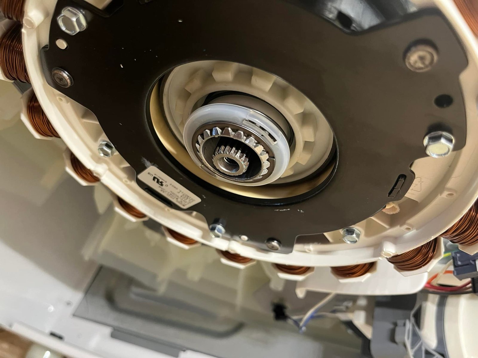
On top load washers, clutch or shifter mechanisms are used to shift from agitate (for the rinse portion) to spin. It generally has to do with how the internal gears inside the gearcase are engaged. When the shifter is in one position, the motor only rotates the agitator around. When it is in the opposing position, it then moves the tub and the agitator at the same time.
While there are a few varieties of shifting mechanisms that you will see depending on the brand that you service, they all serve the same function: To engage or disengage the basket, depending on the phase of the cycle you’re at.
Included here are some images from different brands that you will see in the field.
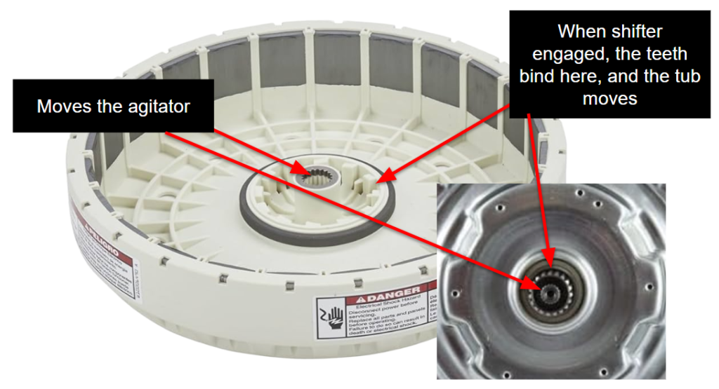
The center teeth on the rotor slide onto the center of the gearcase. The shifter sits on the outer teeth. When the shifter is UP, the teeth on the shifter are not connected to the corresponding teeth on the rotor. So when the rotor spins, it’s JUST spinning the inner section on teh gearcase, which in turn is JUST moving the agitator.
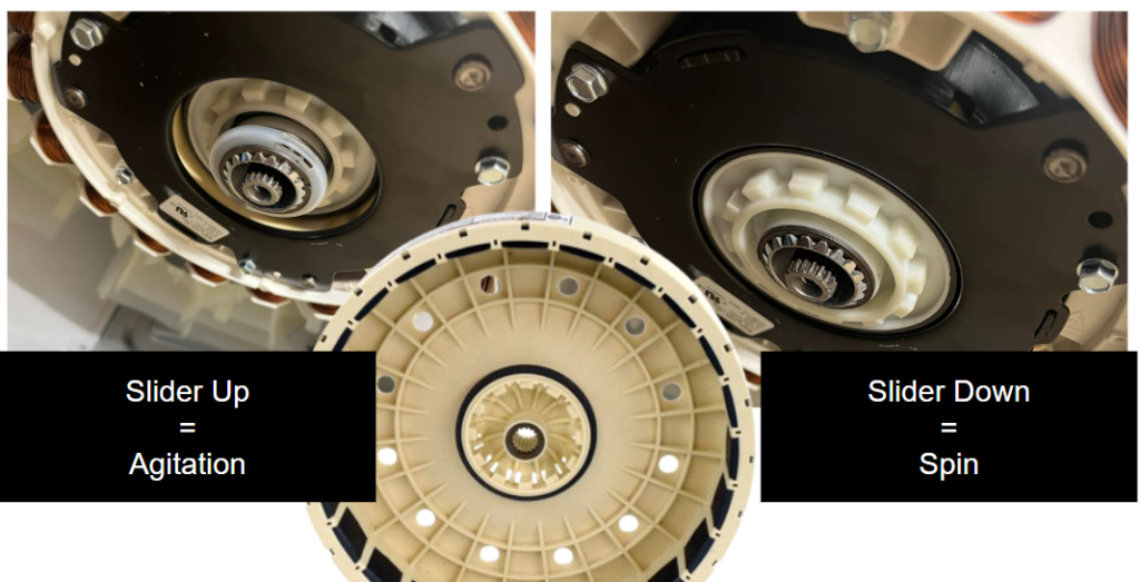
Regardless of if you are working on GE, LG, Whirlpool or Electrolux, when you’re dealing with a shifter mechanism on a top load washer, they’re relatively simple and straight forward.
Missing Neutral
ElectricityIf you’re familiar with Voltage Potential … or voltage in general … then it should not be too hard to determine if you’re missing Neutral with a few quick and easy tests.
Many techs check voltage simply across a load. If they see 120 VAC, then good to go. If they see 0 VAC, then they oftentimes spiral out and start replacing parts. While we alreday have a microlesson on Voltage Potential, let’s look how that concept can show you if you are missing Netural or not with a fake circuit colored in with where Line and Neutral would be, given the visible failure.
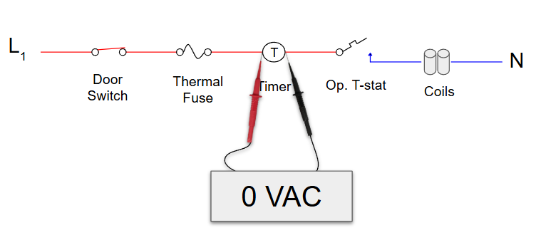
In this example, we can see the Op. T-Stat has opened. Neutral comes through the coils and stops at the T-Stat, before it can reach the timer. And when we have our leads on across the timer, we see 0 VAC. Your initial thought might be that the breaker has tripped, but what if you already checked at the terminal connection and you had the voltage there? Do you just assume it’s the wire harness, or do you make one more test to figure out which direction to focus your efforts?
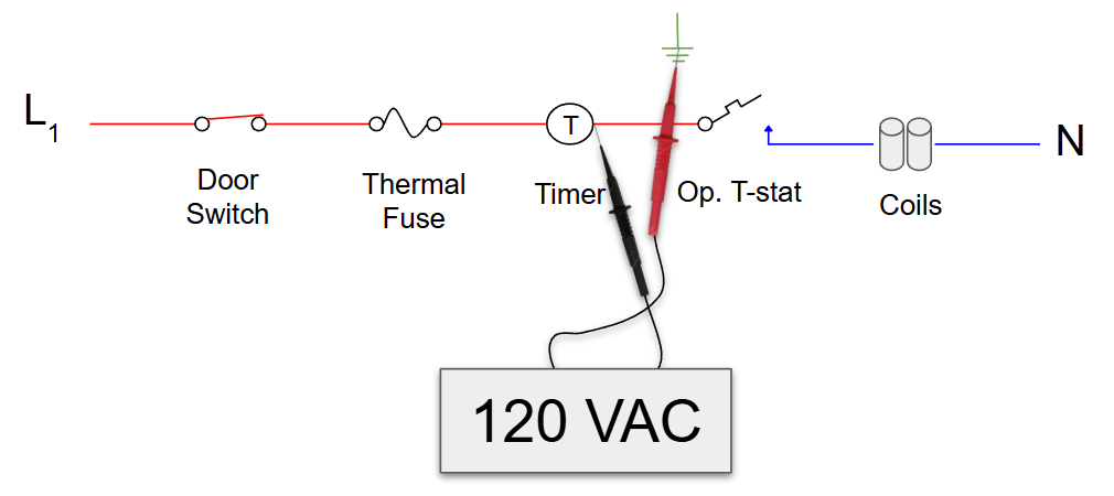
While we don’t have the luxury of wires being colored in when in the field, we do have the luxury of knowing what it means when we see 120 VAC when checking to Ground on the Neutral side of the circuit. Since Ground is a known 0 VAC reference point, this tells us that we are missing neutral.
Know what else that means? It means we no longer need to waste time tracing out wires to see if anything is loose on the Line voltage side. It means we can focus all our efforts on accessing and checking the T-Stat and the coils (per what is in this strip circuit).
Pre-Diagnosing An Appliance
Electricity, GeneralYour dispatch says the washer is not draining. That is it. You don’t know if there’s a humming or if there is nothing happening when the drain pump kicks on.
This scenario usualy plays out in one of two ways:
1) Technician arrives. Finds tub full of water. Manually drains it out so he can tilt the unit back or pull it apart to access the drain pump. Finally, he disconnects the wiring from the drain pump and checks resistance. Might show the needed 20Ω, might show OL. What happens if you see 20Ω? Well, you have to then try to kick on the drain pump, see if it’s getting that 120 VAC. If it isn’t then it’s a matter of tracing the wiring to the board, seeing if there are any broken wires, then landing on the board as the failure.
2) Technician arrives. Pulls open the UI panel to access the board. Disconnects a connector, checks resistance. Sees 20Ω on the drain pump circuit. Plugs that connector back in, backprobes it and tries to kick on the drain pump. Sees the board is not sending voltage. Myabe jumps line and neutral to the drain pump right there and it kicks on and drains the unit.
The difference between scenario 1 and 2: In scenario 2, the tech pre-gamed the call. He reviewed the schematics, he knew where his test points were and he was able to make all his checks and get the unit drained out directly from the control board. Whereas in scenario 1, the technician wasted a lot of time manually draining out the water, tilting it back, making checks that only really showed the drain pump had resistance.
Which category do you fall into?
Pre-gaming a service call might include arriving with the part you think will solve the issue, but good pregaming includes assessing the circuit you think is going to be an issue, and finding the easiest but most comprehensive way to test it. I don’t know about you, but I have little interest in spending 30 minutes defrosting an iced over evaporator just to find out the bi-metal is closed and the heater is testing in spec, when I could have made those checks directly from the board in under 3 minutes.
Understanding wire diagrams and circuits is critical if you want to be an effective appliance repair technician. At Appliance Tech Academy, we do what we can to make learning this stuff easy for you. Because, let’s face it, when you check resistance directly at the load itself (say, the drain pump), guess what you’re missing out on? The wiring between the board and the drain pump. And what happens if the board has failed and is not sending that voltage? While you might feel confident in your assessment after having spent the time draining the washer or defrosting the evap cover, you could have been just as confident … 30 minutes sooner.
Inductive Loads
Electricity, GeneralWhen you test a bake element, you are testing a resistive load. It is simply a wire designed to get hot. Ohm’s Law works perfectly here.
But a washer drain pump, among other loads, is an inductive load. This means it is made of coils of wire wrapped around a core to create an electromagnet. When you mix coils of wire with Alternating Current (AC), the rules change when it comes to Ohm’s Law.
The Problem: You put your meter probes on a drain pump and it reads 20Ω. According to Ohm’s Law, if you apply 120 Volts of AC, you should get 6 Amps of current. But when you clamp around one wire with the drain pump running, you only see 1 amp.
WHY???
Your multimeter uses a tiny, flat DC battery to measure resistance. It only measures the physical copper wire, which is why it reads 20Ω. But the appliance runs on 120 Volts of AC (Alternating Current). Because the current is alternating back and forth 60 times a second, the coil creates a rapidly pulsing magnetic field. This pulsing magnetic field actually acts as a brake! It creates a “counter-voltage” that actively pushes back against the incoming electricity. This magnetic pushback is called Inductive Reactance.
The “Headwind” Analogy: Think of pushing a heavy cart.
- Resistive Load (Bake Element): Pushing the cart on a flat road. Your multimeter easily measures the friction of the road.
- Inductive Load (Drain Pump): Pushing the cart on a flat road, but straight into a massive, invisible headwind.
Your multimeter only measures the road (the 20Ω copper wire). It is completely blind to the wind (the magnetic pushback). Because of that magnetic “headwind”, the total resistance (properly called Impedance) of that drain pump while it’s running is actually 120Ω, which is why it only pulls 1 Amp!
Parallel Resistance
ElectricityResistive loads, be it a 20Ω drain pump or an 18Ω bake element, drop voltage across the resistance of that load. When you put your two meter leads on either side of a working drain pump, this is why you see 120 VAC. The 120 comes in on one side. Neutral, or 0 VAC, comes in on the other side. And the resistance of the load is what drops that 120 across it, so you are not dealing with a short.
Knowing the basics of electricity and circuits can help you to make easy checks from easily accessible test points. And it’s pretty straight forward when you have a single load in a circuit. But what happens when you are making a resistance check on a parallel circuit?
When you are checking resistance on a parallel circuit, the total resistance is always going to measure lower than the lowest resistance of the circuit.
Let’s say you are testing a circuit from the control board that has a 2.2Ω load and a 10Ω load wired in parallel. Instinct might tell you to add those numbers together. But parallel circuits don’t work like that. In parallel, every load you add creates a brand-new path for the current.
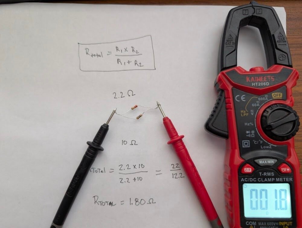
While it might be easy to overthink it, the math behind this is actually really simple.
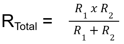
Really, at the end of the day, as an appliance repair technician who is assessing a parallel circuit from, say, the control board, you would need to know the two resistance values of the circuits you are testing. Then so long as the total resistance that you see is just below the lowest one, then you’re good to go! (Yes! It is a bit more nuanced than that, but it’s really not something that you’re going to be testing that often.)
Fuses: Resettable vs. Non-resettable
General, Dryers, ElectricityWhen you have an appliance that uses a heating source, there will be safety measures in place to ensure a fire does not occur. While newer computer controlled appliances will generally incorporate a thermistor for more precise temperature regulation, you will almost always find thermal fuses, thermostats and/or bi-metal switches included as a safety fallback wired in series with the heating source. Consider if the relay on the board fuses shut. We certainly want a way to ensure the heater does not stay on all the time if the element were to ground itself out.
Resettable vs Non-resettable. How do you tell the difference? Well, there are two ways:
1. The wire diagram.
2. The thermal protection device itself.
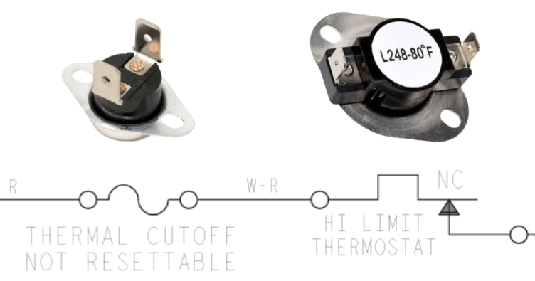
Let’s look at a dryer wire diagram. In line with the heater circuit, among other fuses, we see two different types of thermal protection devices here. One is a non-resettable cutoff, the other is a resettable one. Fortunately, with this diagram, we have the luxury of the diagram calling out one of them as “Not Resettable.”
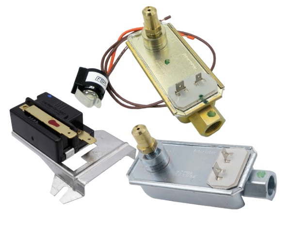
Resettable Thermal Device (Bi-metal)
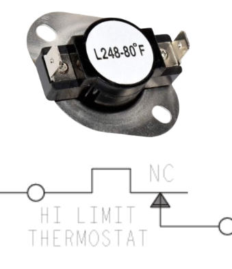
Let’s start with the resettable thermal protection device. For starters, look at the device itself. Notice how it’s relatively large? Inside, there are two bi-metal strips that bend away from one another when heated past a certain temperature. This temperature varies depending on where it’s placed in the unit, so be sure you are ordering and installing the correct one.
And on the schematic (or wire diagram), you can see that the switch is just that: a switch. The line that sits on the arrow is the bi-metal switch. When heated, that switch then opens. When it cools back down, it closes and reestablishes the electrical connection.
Not Resettable Thermal Device
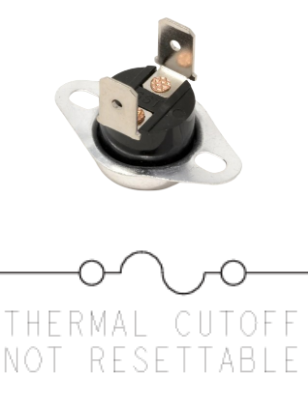
Unlike with the resettable switch, you can see that there are no switch contacts on the diagram here. And also take note of how much smaller the device itself is. There is no need to have the extra space inside for a switch to open and close.
As an appliance repair technician, if you happen across a failed thermal protection device, you need to take the steps to determine WHY they failed to begin with. What happened that caused them to get too hot? Airflow? Grounded Element?
HSI Bake Igniter
Ovens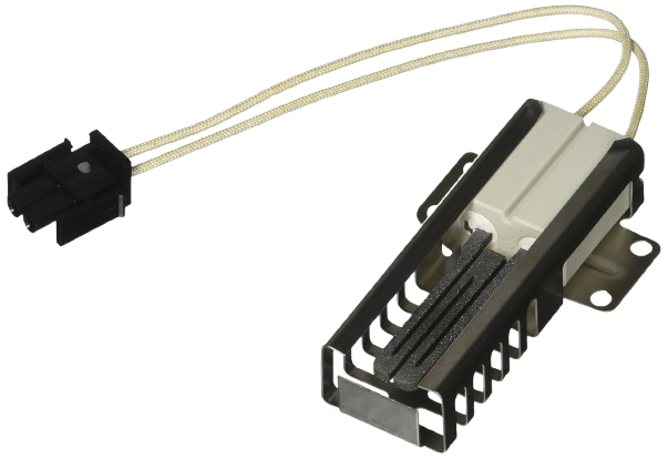
Hot Surface Ignitors (“HSI”, or often referred to as “glowbar”) are used on some ovens to achieve ignition. When energized with 120 VAC, the silicon carbide material glows red hot. When it is emitting enough heat to ensure combustion, the gas valve will release gas into the burner tube.
With this style ignition system on ovens, the igniter remains on when the unit is heating. It is wired in series with the gas valve, and the current draw from the igniter is what keeps the gas valve open and the gas flowing. (Not to be confused with a gas dryer igniter, which goes off after ignition is achieved.)
Given the series cricuit for safety purposes, the HSI igniter needs to be pulling about 3.2 to 3.6 amps to consistently achieve ignition. When you are below that threshold, you will either see no ignition or poor ignition.
Testing The Igniter: Checking resistance across the igniter is not a solid method to determine if the igniter is good. If it’s “open,” then you’ve definitely got a bad igniter, but if you are seeing a resistance valve, you need additional steps to determine if it’s good or bad. When the ingiter is energized, resistance across it drops as the silicon carbide is heated. If there is a crack in the igniter, then it may test good for resistance, but fail when heated.
Other than a close visual inspection, the best way to determine if your igniter is working up to par is by checking the amperage it’s pulling. Clamp your meter around one wire, start a bake cycle. The amperage will start low, then will gradually rise, in accordance with Ohm’s Law.
I = V / R (Current = Volts / Resistance)
The gas valve has a bi-metal inside it. Current flowing through a heater wrapped around the bi-metal inside the gas valve is what causes the bi-metal to bend away, and allows gas into the unit. If the HSI igniter is not pulling enough current to open the bi-metal, we will get no gas, inconsistent ignition, or sputtering combustion, even though the igniter is glowing red.
Water Temp & Detergent
Dishwashers, WashersDishwashers and washers both use detergent to effectuate cleaning. If the detergent does not completely activate, not only will the customer see reduced performance, but they risk having that un-activated detergent activate during subsequent cycles, potentially leading to oversudsing.
Most modern detergents will activate in temperatures of, at minimum, 60-65°F. This means if the customer’s cold water wash in a washing machine is bringing in a brisk 55°F on the cold cycle that they love to use, they are likely to see white streaks on their clothes after the cycle is complete. Despite the customer’s beliefs, this generally does not indicate there is an issue with the washer itself, assuming all other operations are working as they should.
Dishwashers generally rely on hot water to effectuate cleaning. While some models do use an internal heating source to heat the water, on a lot of models, the heater’s primary purpose is to dry the dishes after the cycle is complete, not to heat the cold water. In the Owner’s Manual for the given unit that you are servicing, it will outline the recommended inbound water temperature, which is usually around 120°F.
That said, if you are servicing new appliances and your customer has a “day one” issue that aligns with performance issues, before throwing parts at the repair, be sure to ensure that the unit is getting what it needs to do it’s job. Just because their previous unit did not have issues with the configuration does not mean the new one won’t.
Tech Tip: Dishwashers generally get their hot water from the sink’s hot water supply. It is best practice to run the sink till the water gets hot before starting the dishwasher, that way you are not filling the dishwasher with the cold water.
Bi-Metal
Bi-metals have various purposes in appliance repair. While you’ll generally see them on older units, they are still used on new units here and there, in various applications.
A bi-metal consists of 2 dissimilar metals. When heated, metal bends, so when you incorporate two different metals, they have different temperatures at which they will bend away from one another.
While most commonly known for the bi-metal defrost thermostat for the defrost circuit on fridges, you will also find bi-metals incorporated in flame sensors for gas dryers, resettable thermal limiters for heating applications, and gas valve systems for HSI ignition, among other things.
Important Reminder: While mechanical in nature, bi-metals will have open and close temperatures. If you have a fridge defrost thermostat fresh out of the box at room temperature, it might show open. This does not mean it’s bad. It might just mean that it’s not cold enough for the contacts inside to close.
Bi-metals are commonly used as electrical switches to open and close a circuit based on temperatures. But, in the HSI gas oven heating system, the bi-metal is used for allowing or shutting off gas based on current flow.
And below is a simple flow of when the heater on a defrost system heats up. The bi-metals slowly bend away when heated, and the contacts inside open, thus breaking the circuit.
Voltage Drop
ElectricityWhen 120 or 240 VAC (or any amount of voltage, for that matter) is supplied to a load, that voltage is “dropped” across the load. It’s dropped across the resistance of the load. The load uses all the voltage if it’s the only load or resistance in the circuit.
In a perfect circuit, the Load (your pump, motor, or heater) should be the only thing dropping voltage. If any other part of the circuit—a wire, a switch, or a connector—is dropping voltage, it is “stealing” the pressure your appliance needs to run. This can be loose connections or damaged wires. (Think about the times you’ve seen a fried spade connector at a heating element; this is beacuse it was loose, and was generating resistance.)
Let’s see the application. If you were to place your meter leads on either side of, say, a drain pump that is running, you would expect to see 120 VAC on your meter.
Remember: Voltage is the potential difference between two points. Those two points are where you meter leads are placed — hence the reason you have 2 leads.
Now, what happens if we put a switch on the Neutral side of the circuit. (This could be a switch, or a broken wire, or a failed component in a control board that connects neutral to the circuit.)
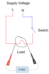
With the switch in the open position, we are getting 0 VAC when we have our meter leads across the same spots as before. The red line has 120 VAC going through it. It’s live. It will bite you if you’re not careful. But why are we not seeing 120 VAC? Why 0 VAC?
When you’re looking at a wire diagram, you will have to trace out how the load is getting its line and neutral. With the diagram above colored in, it’s much easier to understand why we are getting 0 VAC. There is no potential difference in voltage between the two points. You are reading the same side of the line. When a load does not have line and neutral to it, it becomes a simple conductor – no different than a length of copper wire.
Basic Circuit
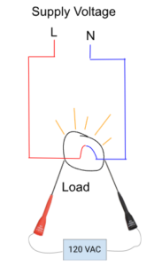
ElectricityA circuit is a complete path in which electricity flows. If the circuit is CLOSED, it is complete. In other words, a closed circuit will cause a load to activate. If you have a line and neutral wired directly to a light bulb, the light bulb will turn on.
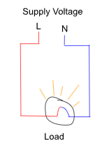
When both line and neutral are supplied to the load (“load” being a light bulb, drain pump, heating element, etc.), you will see Neutral on one side, and Line on the other side. The load is using the full 120 VAC supplied to it to work. The voltage is being dropped across the load.
Now, if we were to put a switch in the circuit, and open it, the circuit would be OPEN. The light would not be on because it is not receiving both line and neutral.
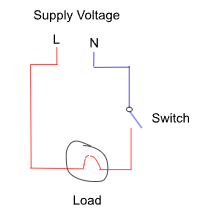
For current to flow, the circuit has to be closed. Current is what is actually gets the load into action.
AC Voltage: 120V vs 240V Explained
Electricity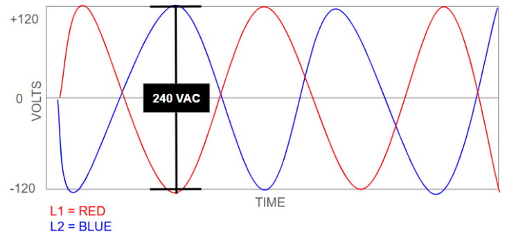
The Basics: Voltage is “Push”
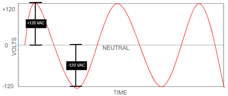
Imagine voltage as water pressure in a hose. It is the electrical “pressure” that pushes current through a circuit. In the US, our homes primarily use Alternating Current (AC), meaning the direction of the “push” flips back and forth 60 times per second (60 Hz). This happens so fast that your meter is really just averaging the voltage, rather than showing you +120 VAC then -120 VAC 60 times every second.
The 120 VAC Reference
Voltage is never a single-point measurement; it is always the difference between two points.
- The Setup: You have one “Hot” wire and one “Neutral” wire.
- The Measurement: When you measure from Hot to Neutral, you see 120V.
- Why? The Neutral is a reference point at zero. The Hot wire is pushing and pulling at 120V relative to that zero.
The 240 VAC “Double Push”
Large appliances like dryers or ovens need more “pressure” to work. We get 240V by using two “Hot” wires instead of one Hot and one Neutral.
- The Secret: These two hots are “out of phase.” When Hot A is pushing at +120 VAC, Hot B is pulling at -120 VAC.
- The Measurement: The distance (difference) between the peak of Hot A and the valley of Hot B is 240V.
The Reference Error
If you measure 120V from Hot to a metal cabinet (Ground), you are using the ground as your reference. If a ground wire is broken or “floating,” your meter might show a ghost voltage or 0V, even if the Hot wire is live and dangerous. Always confirm your reference point.
Why Knowing This Matters
When you’re checking VAC at a load, let’s say a bake element, and you’re seeing 0 VAC across, but 120 VAC on each side to GND, then this should tell you that you’re missing a leg of voltage! (More on that when we discuss Voltage Potential.)
Microlessons
General

Appliance Tech Academy is dedicated to providing those with an interest of learning appliance repair an easy avenue to learn in ways that work for them! In addition to the most robust free training program available, we are now unveiling “microlessons.”
Sitting down to read through hours of coursework is not a luxury many techs have. You might have 5-10 minutes between calls or before work to review some material, but then you have to log in, find where you left off, get back in the mindset, etc.
With the microlessons, these will be available to all, and you don’t have to log in to see them! These microlessons on learning how to repair appliances are added as they are thought of, much in a fashion similar to social media feeds.
Feel free to comment with questions that you have on topics, or provide a thumbs up if you find the content useful!